Friday, December 8, 2017

Fall 2017, Weeks 11-12: Presentations, Final Designs, and Semester Wrap-Up

In these final two weeks of the semester, each project group presented their 3rd and final presentation of the semester. After watching the presentations, it is clear that everyone is a little behind schedule, but I remain optimistic that everyone will be able to finish in the spring.

In terms of project progress, our team has not met our semester goal of rapid prototyping a switch section. Our team had difficulty creating concentric curves with the bending machine in the shop, so we are still trying to determine how to make a prototype. If bending metal is no longer an option, our team is considering the option of using wood. Although this section will not as durable as a metal section, we will be able to test if our design will help the bogie pass the clearance gap.

The final design for the attachment to the switch section can be viewed below. 


This design was chosen because it provides a smooth transition onto the third rail of the system. The third rail can be inserted into the sleeve located on the lower section of the attachment. The results of FEA through SolidWorks shows that the attachment will not fail under the load of multiple bogies pushing against the third rail.

To wrap up the semester, our team is currently completing the final report for the semester. We have also finished the Bill of Materials for our design. Looking to next semester, it is clear that we have a lot of work ahead of us.

Tuesday, November 28, 2017

Fall 2017, Weeks 10-12: Rapid Prototyping and Obstacles

These past few weeks, our team has continued to rapid prototype straight sections for the track. By the end of week 11, our team was able to construct a second straight section. However, with the cost of a single support, our team cannot yet mount the straight sections. Nonetheless, we can begin testing the robustness of our track with the bogie team. 

To minimize the BOM as much as possible, our team is leaning towards reducing the cross section of the aluminum rails to 1'' by 0.25''; previously, it was 1.5'' by 0.25''. We are able to do this because the bogie team's design does not need extra room at the bottom of the track. The reduction of the track's cross section also improves our specification of concentric curves, because it becomes easier to bend, and there are viable bending machines that we can use. 

To be honest, I was hoping to have made a curved section by this point of the project, but the obstacles we are facing in terms of bending machines is to be expected. We are hopeful that this problem will be resolved in the next few weeks.

Friday, November 3, 2017

Fall 2017, Weeks 8 and 9: Presentation 2 and Support Structure

In week 8 of the Spartan Superway project, our team presented our second presentation for the semester. After presenting our material, our peers pointed out that our designed support structure required an additional leveling system for un-leveled ground. My team considered ideas such as drilling holes through the support base to insert 4 adjustable bolts. This would allow us to angle the support as needed.

In week 9, my team continued to rapid prototype various components of the track. We also tested the bending machine in the workshop, and realized that the accuracy of the machine is not suitable for the tolerances of our project. With this complication, my team has to reconsider alternative methods to bend the aluminum. We also had to reconsider the size of aluminum that we would be using for the project. 

Wednesday, October 18, 2017

Fall 2017, Week 7: Final Design Decisions

As we near the start of the rapid prototyping stage, our team must still finalize a few designs. First of all, to clear the gap of the switch, my team and I designed the switch assembly in the figure below.
To overcome the clearance gap of the switch, we decided to introduce a third rail. This third rail consists of three portions: the straight rail which inserts into the switch bracket attachment (in blue), the curved rail, and a wedge, used to support the curved rail. The assembly also needed a middle bracket to support all the weight present around the wedge area; thus, the middle half bracket was created. This geometry was chosen because our team wanted to avoid mounting anything onto the curved area.

The entire 3D model for this track is near completion, but our team is still considering options for how to mount the support beams and brackets. Our hope is to complete this by next week, so that a test model can finally be fabricated. 

Thursday, October 5, 2017

Fall 2017, Weeks 5 and 6: Further Design Work

After completing Presentation 1 of the semester last week, the 1/12 scale team continued further design work for the new track. To tackle the problem of the switch rail, I first calculated the minimum curve radius of the turn. With an assumed front axle rotation of 20 degrees, I found that about an 11 inch curve will allow the bogie to run smoothly. Below is one design option for the switch.

To guide the switch, we are currently revising the idea I had a couple weeks ago. The gap that the bogie must clear is longer than I anticipated, so I decided to go with another design.

By next week, my team and I hope to have a complete Bill of Materials, as well as a concrete solution to supporting the track. 

Sunday, September 24, 2017

Fall 2017, Week 4: Design Work

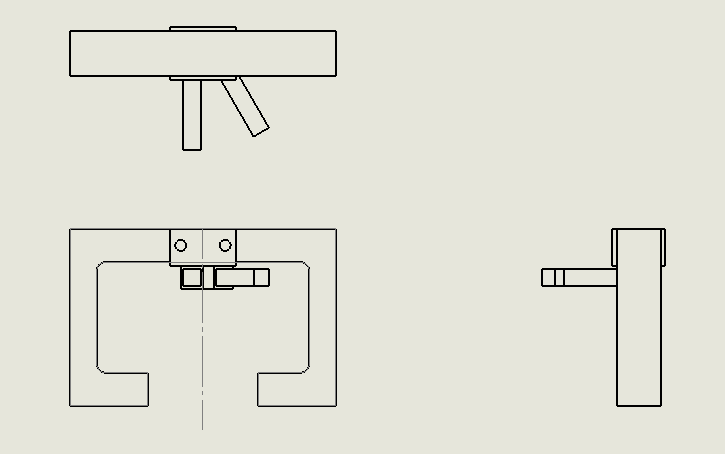
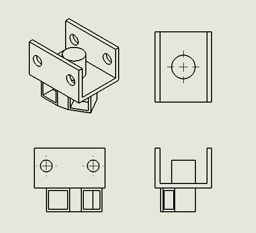
             This week, our team continued to work on designing the switch section of the track. We are devoting a lot of time into this section because without it, the Spartan Superway project will not succeed. I have been working on the support bracket for the area of the switch. (Seen below) The dimensions for this design has not been finalized.


Figure 1: Switch-section bracket

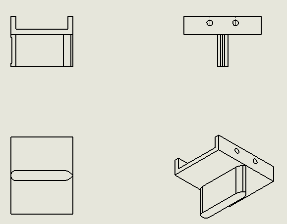
           The switch support bracket will guide the Superway using a divider located at the top of the bracket. My first design utilizes 3 modular parts: the main support bracket, the detachable guide component, and rails.
Figure 2: Detachable component

            This component determines the direction the bogie will follow. The two inserts on the bottom of the part will house the rails to guide the track. 

Monday, September 18, 2017

Fall 2017, Week 3: Presentation Preparation and Further Design Work

          This week, the track team for the 1/12th scale and full scale teams got a glimpse of what the Futran system would look like. In our separate teams, we started to prepare material for our first major presentation of the semester. In addition, we explored options to how the switching mechanism would be achieved on the 1/12th scale model. My main concern for this portion of the project is the stability and integrity of the bogie as it makes the switch. As such, our team has been in constant contact with the bogie team. By next week, I hope to have design sketches or CAD models, so that we can start rapid prototyping.

Spring 2018, Week 15: Completing the Final Presentation

May 9, 2018 On Wednesday, we came into the SSDC to adjust any sections that would cause the bogie to bind. We re-bent a curve section, as ...